Social Icons

Tuesday, January 22, 2013

Team Associated Diff kit rebuild


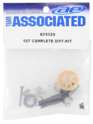
In this write up I will be providing walk through step-by-step instructions on how to assemble or rebuild your Team Associated diff.  Below is the actual kit and also the rebuild kit.
 In my write up I will be will be rebuilding a diff but the assembly of a fresh new diff is the same. 


You will need the following items.  The electric motor spray is only needed to clean parts if you plan on rebuilding a used diff.  The two types of greases will be needed to build the diff.


First, remove the diff from the car and disassemble the kit using an Allen wrench from one side of the diff.


Clean all used parts with the motor spray.  After spraying the parts be sure to wipe clean with paper towel.  I found it easier to spray the towel first before cleaning the balls.  Roll the balls with your finger on the wet paper towel.  Careful, they are easy to lose.  There are two different sizes so beware not to mix them up.

Now it’s time to assemble the diff.
Apply a small bead of clear grease to inside of both outdrives as show below.

After you have applied the grease install one steel plate on each end.  Note: Be sure to line up notch correctly on each plate as shown.

Next, install a small amount of clear grease in each hole of the main gear and install one ball in each hole.  Tip: It makes the job easier to add small amount of grease to the end of a toothpick to pick up each ball and input into hole.

 Then add small amount of clear grease to top and bottom of gear.

Set main gear on shorter outdrive and shown below.  The applied clear grease should stick the gear to the outdrive.  Once you confirm you have the gear on the correct drive place the longer outdrive on top as shown.

The last part of the assembly is to assembler the thrust balls.  There are 7 of these.  Be sure to use the black grease at this time.
Assemble the screw as in the picture below.

Using a bench vise or other tools may help in this next step.  Apply small amount of black grease all the way around top washer as shown.

Using a toothpick again place each of the seven thrust balls around the washer as shown. Once all seven balls have been set correctly place the last small washer on top.

Last step is using the Allen wrench, carefully insert assembled screw into long end of outdrive as shown.

Use something flat to hold other end while you tighten down the diff.  Once the screw is tight stop tightening and back out about a half of a turn.  DO NOT OVER TIGHTEN.

 Use the illustration below to guide how tight to have your diff. 


Monday, December 24, 2012

Cleaning and reviving Traxxas drive Half & spine shafts part #1951

In this write up I will be providing instruction on how to clean and revive those dirty stiff axle sliders in Traxxas vehicles.  Over time dirt and mud gets caught in the slider and the axle will not work properly.  Instead of replacing these items I will show you how to clean them.


First, remove the wheel from vehicle.


Remove pin and washer from sub axle.


Next, remove bolt that hold the camber link.


Drop the axle down and remove the stub axle.


Now that they are separated, using a sharp point hobby knife scrap the inside tracks.  This will remove the hardened mud and build up.  Do this for all the tracks.  Periodically through this cleaning I will slide the axle up and down and it helps remove the buildup. 


Use Rubbing alcohol and water if needs be to clean the parts thoroughly.  Also, I have found that a little sand papering will help as well for those hard build up areas.


After you have cleaned them were the slide very easy then apply a very small amount of oil and wipe the area clean.  The parts should not be oily just enough oil to clean the surfaces.  Too much oil will attract dirt.  The axle should be loose enough to where it will not hold on by itself if the vehicle was tipped. 
Re-assemble in reverse order.  

Basic Soldering Techniques

I have helped so many people solder in my years of RC so I thought I would make a write up on how to solder wires onto a Deans type connector. This seems to be the most common type of connector. These techniques can be used on any type of soldering job. I encourage anyone that is in the hobby to learn how to solder. Soldering is needed a lot and being proficient at it will only help the hobby be more enjoyable First, gather all the parts you need. Have your iron heated up fully before starting.


I will be using strippers, tablevice, and solder.


First, strip your wires so there is about a 1/8 inch of bare wire.  Apply solder to the bare wire so the solder seeps into the wire as shown.


Then add solder to the prong/plug.  This is where people make the mistake.  They try to solder onto a prog without having solder molded onto each piece.  Make sure it latches onto it and not just sitting on like a bubble.  If it’s bubbling then your iron may not be hot enough.


After solder is added to each point then go ahead and apply heat with the iron and wait to the “Bonding” of the solder occurs.  This is where people often don’t let the solder adhere to each item enough.  You will see the solder mold into one piece instantly once enough heat is added.

After this then use the shrink tube that came with the plugs and shrink over the wire.  Note, make sure you put the shrink on wire before soldering or you will have to remove your solder job to put it on.


Sunday, November 4, 2012

Pull String Control System


A Pull String control system works very well.  Make sure you install the pull string BEFORE you cover the plane.  MUCH EASIER!!!

They are easier to adjust and don’t strip your servo as easily as the traditional push piano wire system does. In this write up I will explain how to install a String Pull system in your plane.  This is more commonly used on the elevator and rudder.  You just need some aluminum tubing and string.  The string can be purchased from any fabric store.  Be sure to get strong polyester string.  Pull on it hard to ensure it will not break easily. 

In the picture below you will see how the string looks after its installed, keep in mind you will need to build custom control horns as in my other write up.


In the next picture below you will notice that the string route through the servo horn and back to the other side of the control horn. 
Don’t get intimidated by this as once you do it the next time is a breeze and you will learn to love the system.  You can use small washers in place of these fancy custom plates that are mounted under the servo screw to hold the string in place.  To adjust all you need to do is loosen the screw and adjust.  Simple!! 


Now, here is the tricky part.  You are probably saying to yourself there are not enough strings to loop around each elevator horn, right?  Well let me explain.  The elevator servo will have two string ends coming from it.  You will need to tie a “Y” off of each string end.  One “Y” will route through to the top of the elevator and the other “Y” will route to the bottom.  Make sense? 

Here is another picture


Notice how the string has to hook to both sides of the horn.  This is because it is a Pull system not a Push system.  This is one side of the elevator.  You will need to do this to both sides.


To secure the string all you need to do is wrap around horn and then use a small drop of CA to secure the string.  Then tie a knot.  The CA allows you to pull the string tight and hold it in place while you tie the knot.  If you don’t CA before tying the knot you will be fighting to keep the string tight. Allow enough loop to be able to remove the string off horn if you ever need to.  I usually tie my knots about ½ to 1 inch from horn.


This will take patience and practice.  Use aluminum tubing to route the string through the fuse.  Be sure to debur the tubing so rough spots don’t cut the string. 


Saturday, October 13, 2012

Installing cable system for ailerons


In a previous write up I showed you how to cut out and build your ailerons.  There are several ways to set up your ailerons and “power” them.  One of the more common ways is to use piano wire where each wing will have its own dedicated servo.  This way works great but requires more work and doesn't seem to work as well. 
 In this write up we will be using a Push Cable made by Sullivan.  This size is .032 w/Gold-N-Clevis 36”
*Please realize that if you choose this method you will not have flap-working ailerons.


This method works very well and the ailerons move very smooth and are easy to adjust.  I highly recommend this method. 

After ailerons are cut out and built you will need to decide on the placement of the cable.  Make sure you are not making sharp bends in the cable as you need the cable to flow smoothly in the cable tubing.  See picture below on my placement. 


You will need to decide on the servo placement so it doesn't interfere with the other components in the fuselage.  The cable should be placed straight through the ribs.  Using a little drill bit you can drill these holes through the ribs by rolling the drill bit with your fingers.  Once the cable is in place use medium CA (NOT thin) to glue the cable in place.  You will have to cut the tubing to allow the E-Z connect that mounts to servo wheel.

Mount a small balsa plate that the end of the wire can mount to.  Trim off excess tubing as shown below.  Be sure not to glue the cable to the tubing.  Use small amount of CA.  Use Caution!!


The last step is to mount the control arm to the aileron.  Then I use DuBro E-Z connector and mount the connector in the arm.  Then the wire routes through the E-Z connector for easy adjustment.


About Us

cameron.hobbyon@gmail.com